At Katalyst Engineering Services, we continually strive to drive innovation by deftly utilizing these resources, changing the issues encountered by various industries and fields with potential solutions.
At Katalyst Engineering Services, we continually strive to drive innovation by deftly utilizing these resources, changing the issues encountered by various industries and fields with potential solutions.

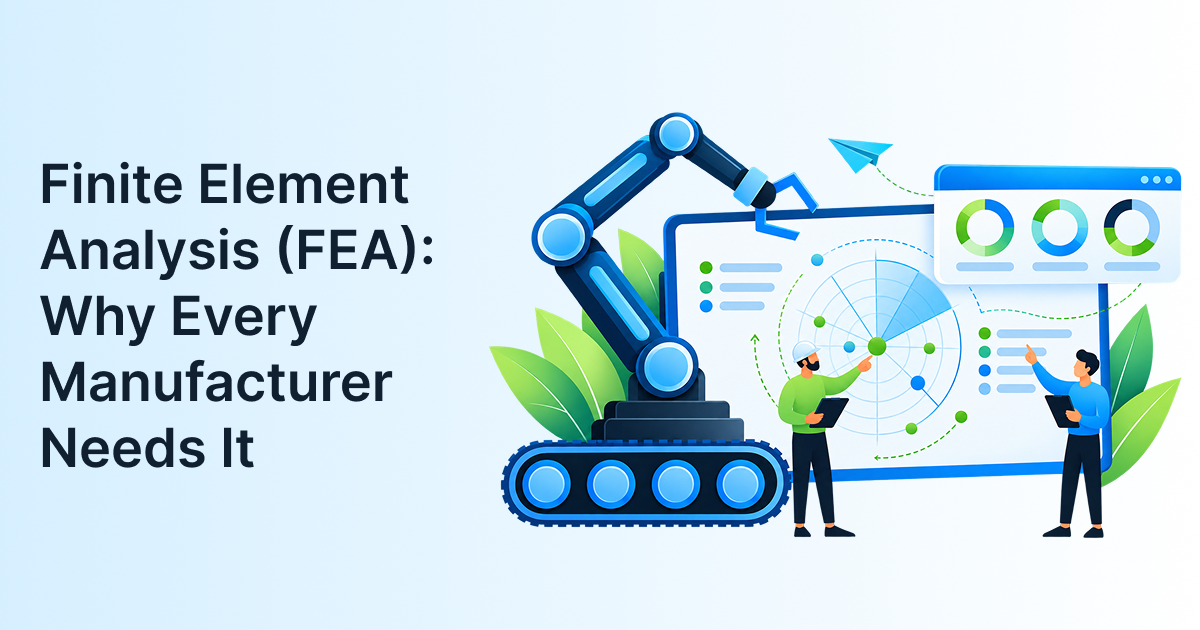
To reduce product failures, development costs, and late-stage design changes, manufacturers need finite element analysis (FEA). FEA uses engineering simulation to predict how a part or assembly will respond to real loads, heat, vibration, and other operating conditions before production begins.
For manufacturers, the value of finite element analysis is not the software itself. It is the ability to make better decisions earlier; before a design is released for tooling, production, or customer use. This is why FEA has become a core part of modern manufacturing engineering services, alongside design, validation, and production support.
Did you know?
FEA is used not only to verify product designs but also to simulate manufacturing processes such as forming, machining, and joining. These simulations can estimate residual stresses created during production and feed that information back into the design process.
Finite element analysis is a computer-based method that divides a complex part into many small, connected pieces called finite elements. By calculating how each element behaves under defined conditions, engineers can estimate stress, deformation, temperature, vibration, and fatigue life across the full component.
In simple terms, FEA lets engineers “virtually test” a design before making it. Instead of waiting for a prototype to bend, crack, overheat, or wear out, the team can see where problems are likely to occur and change the design early.
This process is often called finite element modeling. The model includes geometry, material properties, loads, supports, contact conditions, and other assumptions needed to represent real-world behavior.
Every manufacturer needs FEA because physical testing alone is slow, expensive, and often unable to show why a failure happens. FEA gives engineering teams visibility into internal stresses and performance limits that cannot be easily observed on a physical part.
A bracket may pass a basic load test, but FEA can reveal a concentrated stress area that could lead to cracking after repeated use. Housing may look strong enough, but thermal simulation may show expansion that affects seals, bearings, or alignment.
FEA is especially valuable when:
FEA can identify structural, thermal, vibration, and fatigue-related issues before a product reaches the shop floor. The most common problems it detects are high-stress areas, excessive deflection, weak joints, thermal hotspots, resonance risks, and early fatigue failure.
For example, in a sheet-metal enclosure, FEA may show that a mounting area deflects too much under vibration. In a machined component, it may identify a sharp corner where stress concentrates. In a welded frame, it can highlight areas where repeated loading may eventually cause cracking.
These findings help engineers adjust thickness, add ribs, change fillets, revise material selection, or improve the support arrangement before production tooling is finalized.

The FEA process works by translating a real engineering problem into a numerical model, applying realistic conditions, and interpreting the results. A reliable analysis follows a structured sequence rather than simply running software and accepting the first result.
The last step matters most. FEA should support engineering judgment, not replace it.
FEA can be highly accurate, but only when the model reflects the real product and operating conditions. Accuracy depends on correct geometry, material data, boundary conditions, mesh quality, and validation against known results.
A simulation with incorrect support or unrealistic loads can produce impressive looking but misleading results. That is why experienced engineering teams use FEA alongside hand calculations, prototype testing, and physical measurements.
NIST notes that comparing simulation results with physical tests in a consistent way improves simulation quality and robustness.
In practice, FEA is best used to narrow down design options and identify likely failure modes. Critical or safety-related designs should still receive targeted physical validation.
FEA benefits manufacturers in most applications where failure, weight, heat, vibration, or durability directly affect cost and performance. Common use cases include machinery, automotive components, industrial equipment, consumer products, medical devices, and energy systems.
Typical applications include:
For a deeper look at how simulation supports design decisions, see this guide on FEA for design validation.
FEA reduces manufacturing costs by preventing expensive mistakes before they reach tooling, production, or the field. A design issue found during simulation may require a CAD change; the same issue found after tooling may require rework, scrapped parts, delayed launch, or warranty claims.
The financial benefit comes from four areas:
Industry research estimates that virtual prototyping through FEA can reduce physical testing cycles by roughly 40–60%, while helping lower overall product development costs by 25–40%.
The most common FEA mistakes are unrealistic load assumptions, incorrect boundary conditions, missing validation, ignoring manufacturability, and insufficient fatigue assessment. These errors can make a simulation look acceptable while the actual part fails in production or service.
FEA is only as reliable as the engineering assumptions behind it. A model can produce clean stress plots and still be wrong if it does not represent how the part is loaded, supported, manufactured, or used over time.
Unrealistic Load Assumptions
Many FEA errors begin with loads that do not match real operating conditions. A team may apply a single static load when the product experiences shock loads, vibration, thermal expansion, uneven contact, or repeated cycling.
For example, a conveyor bracket may be analyzed for its rated weight but not for the impact created when a heavy item is dropped onto the belt. The simulation may show acceptable stress, while the real bracket cracks at the weld or mounting point.
The practical rule is simple: define the worst, realistic load case, not just the average or ideal case.
Incorrect Boundary Conditions
Boundary conditions define how a part is held, supported, or connected in the simulation. If these conditions are too rigid, too loose, or do not reflect the actual assembly, the results can be misleading.
A bolted joint, welded frame, bearing seat, or rubber mount does not behave like perfectly fixed support. Over-constraining a model can hide deformation and create artificial stiffness, while under-constraining it can exaggerate movement and stress.
Before accepting results, engineers should ask: Does this support condition match how the part is installed?
Using Simulation Without Validation
FEA should guide decisions, but it should not be treated as unquestionable proof. A simulation becomes more reliable when its results are compared with hand calculations, prior to testing data, physical measurements, or a known reference case.
For example, if FEA predicts a deflection of 2 mm, but a simple beam calculation predicts a very different result, the model setup should be reviewed before the design is released. Validation is especially important for safety-critical parts, fatigue-sensitive components, and designs with complex contact or material behavior.
A useful approach is to validate the model first, then use it to compare design options and identify risk areas.
Optimizing Only for Stress While Ignoring Manufacturability
A design may pass FEA with low stress but still be difficult or expensive to manufacture. Thin sections, deep pockets, sharp internal corners, tight tolerances, difficult weld access, or complex geometry can create production problems even when the simulation result looks good.
This is where FEA needs to work alongside design-for-manufacturability thinking. A part should not only survive the load; it should also be practical to cast, machine, form, weld, assemble, inspect, and maintain.
The best simulation outcome is a design that is both structurally sound and manufacturable at the intended volume and cost.
Insufficient Fatigue Assessment
A part may survive one maximum load but fail after thousands or millions of smaller load cycles. This is why fatigue assessment is critical for components exposed to vibration, repeated operation, pressure changes, thermal cycling, or fluctuating loads.
Stress plots alone do not always reveal fatigue risk. A localized stress concentration near a hole, fillet, weld, or thread can become a crack initiation point over time.
For fatigue-sensitive components, engineers should review cyclic loads, stress concentrations, material fatigue data, surface condition, and expected service life—not just the peak static stress.
Yes. Small manufacturers can benefit from FEA because it reduces the risk of committing limited resources to a design that may fail later. Even a focused analysis of one critical component can prevent costly tooling revisions or product returns.
A smaller team may not need simulation for every part. The practical approach is to prioritize components with high loads, safety implications, repeated failures, complex geometry, or significant production cost.
Outsourced FEA simulation services can also give smaller manufacturers access to specialized engineering simulation services without investing heavily in software, licenses, and simulation specialists.
FEA Versus Physical Testing
FEA and physical testing solve different problems. FEA is fast, flexible, and useful for exploring many design options; physical testing confirms real-world performance and validates assumptions.
| Factor | Finite Element Analysis | Physical Testing |
| Best used for | Early design exploration and risk identification | Final validation and real-world confirmation |
| Speed | Fast once the model is set up | Slower due to samples, fixtures, and test setup |
| Cost | Lower for multiple design iterations | Higher for repeated prototypes and tests |
| Visibility | Shows internal stress, deformation, heat, and vibration | Shows observable performance and failure |
| Flexibility | Easy to test multiple load cases and design changes | Limited by physical samples and test conditions |
| Limitation | Depends on assumptions and model quality | May not explain the root cause of failure |
The strongest product-development approach uses both: FEA to guide design decisions early, and targeted testing to confirm the final design.
Manufacturers should look for FEA services that focus on engineering outcomes, not just software execution. A good provider should understand the product, manufacturing process, loads, materials, and the decisions the analysis needs to support.
Key capabilities include:
When evaluating finite element analysis services, ask how the team validates models and how results will influence the design. The answer should include assumptions, limitations, and next steps; not only a report of maximum stress.
If you’re unsure whether your design can withstand operating loads, vibration, thermal exposure, or fatigue conditions, an engineering assessment can help identify risks before production investment begins.

At Katalyst Engineering, FEA is treated as part of a broader engineering and manufacturing solutions workflow. The goal is to help product teams understand risk early, improve designs with confidence, and move toward production with fewer surprises.
Simulation is most useful when it is connected to design intent, manufacturing reality, and validation. That means reviewing not only whether a part survives a load, but whether it can be manufactured consistently, assembled correctly, and performed reliably in service.
If you are developing a new product, facing repeated failures, or preparing a design for production, talk to our engineering team. A short discussion about your part, loads, and manufacturing constraints can help determine whether FEA is the right next step.
1. What is finite element analysis in simple terms?
Finite element analysis is a computer simulation method that predicts how a part will behave under real conditions. It breaks a component into small elements and calculates stress, movement, heat, vibration, or fatigue across the design.
2. Why do manufacturers use FEA?
Manufacturers use FEA to find design problems before production. It helps reduce prototypes, prevent failures, improve durability, optimize material use, and avoid expensive late-stage changes.
3. Can FEA replace physical testing?
No. FEA should not completely replace physical testing, especially safety-critical products. It is best used to guide design decisions early, while physical testing validates the final design under real conditions.
4. How accurate is finite element analysis?
FEA can be very accurate when the model uses correct geometry, materials, loads, supports, and mesh settings. Results should always be checked against calculations, test data, or known engineering behavior.
5. What types of problems can FEA detect?
FEA can detect high-stress areas, excessive deflection, thermal hotspots, vibration issues, fatigue risks, weak joints, and potential failure points before a product is manufactured.
6. When should a manufacturer use the FEA?
A manufacturer should use FEA when a part carries significant loads, experiences of vibration or heat, has safety requirements, or would be costly to redesign after production begins.
7. What is the difference between FEA and finite element modeling?
Finite element modeling is the process of creating a simulation model. Finite element analysis is the broader process of using that model to study performance and make engineering decisions.
8. Do small manufacturers need FEA?
Yes, but they do not need to simulate every part. Small manufacturers can focus FEA on critical components were failure, rework, warranty cost, or safety risk would be high.

Senior Vice President, Katalyst Engineering
Bhavik Shah is the Vice President of Global Engineering and Manufacturing at Katalyst Engineering, with over 22 years of experience in the engineering industry. He specializes in product development, R&D, and engineering delivery operations, driving innovative, design-led solutions across automotive, industrial, and off-highway sectors. Bhavik plays a key role in strengthening engineering strategies, building global partnerships, and delivering high-performance outcomes for clients.