At Katalyst Engineering Services, we continually strive to drive innovation by deftly utilizing these resources, changing the issues encountered by various industries and fields with potential solutions.
At Katalyst Engineering Services, we continually strive to drive innovation by deftly utilizing these resources, changing the issues encountered by various industries and fields with potential solutions.

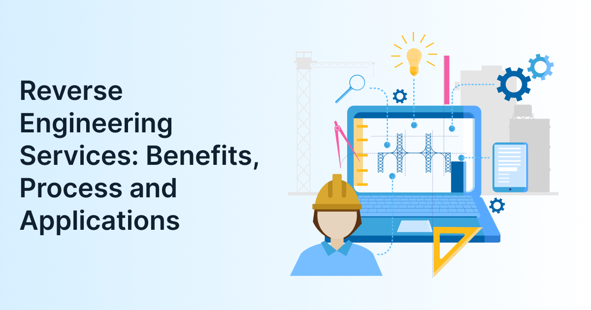
Reverse engineering services help manufacturers recreate, understand, and improve physical parts when original drawings, CAD files, or design documentation are missing. Using 3D scanning, measurement data, and CAD reconstruction, engineers can turn an existing component into a usable digital model for repair, redesign, inspection, or production.
For manufacturers dealing with obsolete machinery, damaged components, supplier gaps, or undocumented equipment, reverse engineering is often the fastest way to restore continuity. It is also a practical engineering service within broader mechanical engineering services, especially when a part must work reliably in its real operating environment; not merely look correct on screen.
Did you know?
The global 3D scanning market was valued at USD 4.28 billion in 2024, as per Grand View Research report and is projected to grow at a CAGR of 10.1% from 2025 to 2030, driven by industrial metrology, automotive inspection, and reverse engineering.
Reverse engineering services convert a physical component into accurate digital engineering data. Instead of beginning with a design file, engineers measure or scan the existing part, reconstruct its geometry in CAD, and validate the result for its intended use.
The purpose is not simply to copy a shape. A well-executed reverse engineering workflow recovers dimensions, features, tolerances, material assumptions, and manufacturing requirements. That difference matters because a scanned surface may look accurate but still fail if wall thickness, fit, load path, or production method is not properly reviewed.
Reverse engineering is commonly used when –

The reverse engineering process moves from a physical part to a validated, production-ready CAD model. While every project is different, most workflows follow the same engineering sequence: capture geometry, reconstruct the model, check accuracy, and prepare the design for manufacturing.
1. Define the purpose of the model
Before scanning begins, engineers need to know what the CAD model will be used for. A model for visual documentation requires less detail than one intended for CNC machining, casting, molding, or 3D printing.
This early decision affects scanner selection, measurement accuracy, tolerance strategy, and the level of CAD reconstruction required.
2. Capture the physical geometry
Engineers use 3D scanning, structured light scanning, laser scanning, CMM measurement, or CT scanning depending on the part. Surface scanning captures external geometry as point-cloud data, while CT scanning can also reveal internal features that cannot be seen from outside.
ZEISS notes that 3D scan data can support reverse engineering, dimensional inspection, digital twin creation, and CAD-ready file generation for legacy or prototype parts.
3. Clean and align the scan data
Raw scan data is rarely usable on its own. Engineers remove noise, align individual scans, merge datasets, and create a reference surface from the point cloud.
Accuracy is protected at this stage. Poor alignment, incomplete coverage, or ignored deformation can produce a model that appears correct but does not fit during assembly.
4. Reconstruct the CAD model
The cleaned scan data is converted into a usable CAD model. Depending on the project requirement, the output may be a mesh model, surface model, or editable parametric CAD model.
Parametric CAD is useful when future design changes; feature-level editing, or manufacturing modifications are expected. It allows engineers to adjust dimensions, add tolerances, correct worn areas, and adapt the design for a specific production process.
A mesh or surface model may be sufficient for other applications, such as visual documentation, 3D printing preparation, inspection reference, or archival records. The right output depends on how the model will be used, the manufacturing process involved, and the level of design flexibility required.
5. Validate the model against the real part
The reconstructed CAD model is compared with the scanned part through deviation analysis. This shows where the model differs from the physical component and helps engineers decide whether the variation is acceptable.
Validation becomes especially important for mating parts, sealed assemblies, rotating components, and parts exposed to load, vibration, or heat.
6. Prepare the part for manufacturing
Finally, the model is prepared for its intended production route. This may include machining allowances, draft angles, fillets, wall-thickness corrections, tolerance callouts, and manufacturing drawings.
This is where reverse engineering connects closely with design-for-manufacturability. A recreated part should not only match the original geometry; it should also be practical to make, inspect, assemble, and maintain. Katalyst explains this connection in more detail in its guide to design for manufacturability.
Reverse engineering gives manufacturers a reliable way to recover missing design data, reduce downtime, and improve existing products. Its value extends well beyond replacing a single failed component.
Recover lost or missing design data
Many older machines, tools, and components were manufactured before digital CAD became standard. Reverse engineering creates a digital record of the existing part, making future repairs and replacements easier to manage.
Reduce downtime for critical equipment
When a machine stops because of a broken or unavailable part, waiting for a new OEM component can be expensive. Reverse engineering helps teams understand the failed part and move toward a replacement or improved version.
Support product improvement
Reverse engineering is not only used for replacement. Engineers can scan an existing product, identify weaknesses, test design changes, and develop an improved version without starting from zero.
Improve quality control
A CAD model created through reverse engineering can support inspection, first-article verification, assembly checks, and comparison between design intent and manufactured parts.
Enable digital twins and better documentation
Accurate scan-based models can contribute to a digital twin when they are integrated with relevant asset information, maintenance records, operational data, or other plant systems. On their own, scan data and CAD models provide an accurate geometric representation of a part, but they do not automatically create a digital twin.
Scan-based reverse engineering can still support maintenance planning, plant documentation, inspection, repair, and asset management. Fraunhofer IPK describes scan-based reverse engineering to map real-world objects in their “as-is” state for inspection, repair, and service processes.
Reverse engineering applications are widespread, but they create the most value in industries where precision, equipment reliability, and long product lifecycles are critical.
| Industry | Common reverse engineering applications |
| Automotive | Legacy vehicle parts, tooling, prototypes, performance components |
| Aerospace | Complex components, repair documentation, obsolete part replacement |
| Manufacturing | Machine parts, jigs, fixtures, molds, dies, and production tooling |
| Energy | Turbine components, pumps, valves, and plant equipment |
| Medical devices | Custom implants, surgical tools, and device prototypes |
| Consumer products | Product benchmarking, redesign, and prototype development |
| Construction and heritage | Structural components, restoration work, and as-built documentation |
Reverse engineering is most useful when the physical part exists, but reliable design data does not, or when available data is incomplete, outdated, or no longer reflects the actual component.
It is especially valuable when –
It is not always the right answer. If the original design is inefficient, unsafe, or difficult to manufacture, redesigning the part from functional requirements may be a better approach than copying it exactly.
Accuracy in 3D scanning and reverse engineering depends on the scanning method, part condition, surface finish, operator skill & the intended use of the final CAD model. A scan may capture geometry precisely, but the final model is only useful if it meets the required tolerances and functional needs.
Reflective, transparent, or highly detailed surfaces may require special preparation or a different scanning approach. Internal channels, thin walls, and enclosed assemblies may need CT scanning rather than surface scanning alone.
A practical rule is to define tolerance requirements before scanning. If a replacement shaft must fit within a bearing assembly, the team needs to know the allowable deviation; not simply obtain a visually accurate 3D model.
If you are wondering whether a 3D scan alone is enough to recreate a part, the short answer is no. A scan captures geometry, but engineers still need to validate tolerances, materials, fits, and manufacturing requirements before the part can be produced reliably.
Reverse engineering is an engineering process; copying is only an outcome. The difference lies in understanding, validation, and responsible use.
| Aspect | Reverse engineering | Simple copying |
| Purpose | Understand, recreate, validate, or improve a part | Reproduce appearance or geometry |
| Engineering input | Material, tolerance, fit, load, and manufacturing review | Often limited to scanned geometry |
| Output | Editable CAD, drawings, inspection data, manufacturing-ready model | Mesh or basic 3D file |
| Quality outcome | Can improve reliability and manufacturability | May reproduce defects or poor design choices |
| Legal consideration | Requires respect for IP, patents, and contractual restrictions | Can create infringement risk |
Responsible reverse engineering always considers intellectual property. It should be used for legitimate purposes such as maintenance, interoperability, replacement of owned equipment, benchmarking, or engineering analysis; not to reproduce protected products without permission.
The right reverse engineering partner should offer engineering capability, not just scanning equipment. A scanner can capture data, but it cannot decide whether the reconstructed part will function correctly in service.
Before starting a project, ask –
A capable engineering team should explain these decisions clearly and connect the reverse engineering output to production. When assessing partners, it also helps to review how they handle scope, communication, technical ownership, and delivery, areas covered in Katalyst’s guide on choosing the right engineering team.
Katalyst treats reverse engineering as an engineering problem, not just a scanning task. The focus is on understanding what the part must do, how it is made, and what changes may improve its performance or manufacturability.
Depending on the requirement, the deliverable may include more than a CAD file. It can include inspection data, manufacturing drawings, tolerance recommendations, material guidance, DFM feedback & support for production planning.
This approach is useful for manufacturers who need a part to work again quickly; but also want to avoid repeating the same failure or design limitations in the future.
If you are asking whether reverse engineering can improve an old part rather than simply replace it, yes. Once the geometry is reconstructed in CAD, engineers can review weak areas, correct manufacturability issues, and prepare an improved version for production.
Key Takeaways

Reverse engineering is most valuable when it goes beyond recreating geometry and helps manufacturers make better engineering decisions. Whether the goal is to replace an obsolete component, document legacy equipment, improve a product, or prepare a part for production, the process should combine accurate scan data with practical engineering validation.
If you have a part that needs to be recreated, improved, or documented, Katalyst Engineering can help you assess the right approach and move from physical component to production-ready engineering data. You can contact our team to discuss your requirement.
1. What are reverse engineering services?
Reverse engineering services recreate a physical part in digital form when original design data is missing or incomplete. Engineers scan or measure the component, reconstruct it in CAD, validate the geometry, and prepare it for inspection, repair, redesign, or manufacturing.
2. How does 3D scanning and reverse engineering work?
3D scanning captures the surface of a physical object as point-cloud data. Engineers then clean and align that data, reconstruct it into CAD geometry, compare it with the original part, and prepare the model for its intended use.
3. Can reverse engineering recreate a part without drawings?
Yes. Reverse engineering is commonly used when drawings or CAD files are unavailable. The physical part becomes the source of geometry, while engineering review adds the tolerances, materials, and manufacturing details needed for a reliable replacement.
4. What are the main benefits of reverse engineering?
It helps manufacturers recover lost design data, reduce equipment downtime, replace obsolete components, improve existing products, support inspection, and create better documentation for maintenance and production.
5. Is reverse engineering legal?
It can be legal when used for legitimate purposes such as maintaining owned equipment, replacing obsolete parts, interoperability, or engineering analysis. However, it must respect patents, copyrights, trademarks, contracts, and other intellectual-property rights.
6. How accurate is reverse engineering?
Accuracy depends on the scanning technology, part condition, measurement method, and reconstruction process. A scan may be highly accurate, but the final CAD model must still be validated against the required tolerances and functional needs.
7. Which industries use reverse engineering the most?
Automotive, aerospace, manufacturing, energy, medical devices, consumer products, and construction commonly use reverse engineering for legacy parts, tooling, inspection, redesign, and equipment documentation.
8. What is the difference between reverse engineering and 3D printing?
Reverse engineering creates or recovers the digital model of an existing part. 3D printing is one possible manufacturing method that can use that model. Many reverse engineering projects end with CNC machining, molding, casting, or conventional fabrication instead.

Senior Vice President, Katalyst Engineering
Bhavik Shah is the Vice President of Global Engineering and Manufacturing at Katalyst Engineering, with over 22 years of experience in the engineering industry. He specializes in product development, R&D, and engineering delivery operations, driving innovative, design-led solutions across automotive, industrial, and off-highway sectors. Bhavik plays a key role in strengthening engineering strategies, building global partnerships, and delivering high-performance outcomes for clients.